- 您现在的位置:买卖IC网 > Sheet目录1194 > ADT7473ZEVB (ON Semiconductor)BOARD EVALUATION FOR ADT7473
�� �
�
�ADT7473�
�THERM� LIMIT�
�0.25� 5� C�
�12� V�
�12� V�
�THERM� LIMIT�
�TEMP�
�TACH�
�10� k� W�
�4.7� k� W�
�10� k� W�
�12� V�
�FAN�
�THERM�
�MONITORING�
�CYCLE�
�ADT7473/�
�ADT7473� ?� 1�
�PWM�
�3.3� V�
�10� k� W�
�Q1�
�NDT3055L�
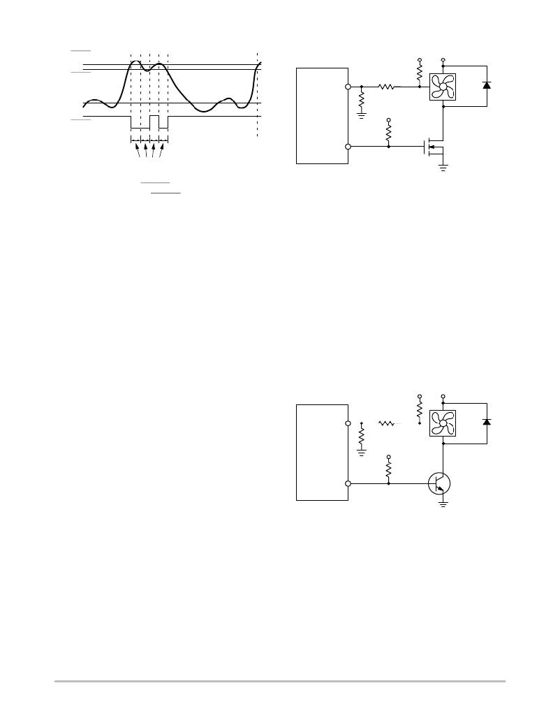
�Figure� 34.� Asserting� THERM� as� an� Output,� Based� on�
�Tripping� THERM� Limits�
�Fan� Drive� Using� PWM� Control�
�The� ADT7473/ADT7473� ?� 1� uses� pulse-width� modulation�
�(PWM)� to� control� fan� speed.� This� relies� on� varying� the� duty�
�cycle� (or� on/off� ratio)� of� a� square� wave� applied� to� the� fan� to�
�vary� the� fan� speed.� The� external� circuitry� required� to� drive� a�
�fan� using� PWM� control� is� extremely� simple.� For� 4-wire� fans,�
�the� PWM� drive� might� need� only� a� pullup� resistor.� In� many�
�cases,� the� 4-wire� fan� PWM� input� has� a� built-in� pullup� resistor.�
�The� ADT7473/ADT7473� ?� 1� PWM� frequency� can� be� set� to�
�a� selection� of� low� frequencies� or� a� single� high� PWM�
�frequency.� The� low� frequency� options� are� usually� used� for�
�3-wire� fans,� while� the� high� frequency� option� is� usually� used�
�with� 4-wire� fans.�
�Note� that� care� must� be� taken� to� ensure� that� the� PWM� or�
�TACH� pins� are� not� connected� to� a� pullup� supply� greater� than�
�3.6� V.�
�Figure� 35.� Driving� a� 3-wire� Fan� Using�
�an� N-channel� MOSFET�
�Figure� 35� uses� a� 10� k� W� pullup� resistor� for� the� TACH�
�signal.� This� assumes� that� the� TACH� signal� is� an�
�open-collector� from� the� fan.� In� all� cases,� the� TACH� signal�
�from� the� fan� must� be� kept� below� 3.6� V� maximum� to� prevent�
�damaging� the� ADT7473/ADT7473� ?� 1.� If� uncertain� as� to�
�whether� the� fan� used� has� an� open-collector� or� totem� pole�
�TACH� output,� use� one� of� the� input� signal� conditioning�
�circuits� shown� in� the� Fan� Speed� Measurement� section.�
�Figure� 36� shows� a� fan� drive� circuit� using� an� NPN�
�transistor� such� as� a� general-purpose� MMBT2222.� While�
�these� devices� are� inexpensive,� they� tend� to� have� much� lower�
�current� handling� capabilities� and� higher� on� resistance� than�
�MOSFETs.� When� choosing� a� transistor,� care� should� be� taken�
�to� ensure� that� it� meets� the� fan’s� current� requirements.�
�Ensure� that� the� base� resistor� is� chosen� so� that� the� transistor�
�is� saturated� when� the� fan� is� powered� on.�
�Many� fans� have� internal� pullups� connected� to� the�
�12� V�
�12� V�
�TACH/PWM� pins� to� a� supply� greater� than� 3.6� V.� Clamping�
�or� dividing� down� the� voltage� on� these� pins� must� be� done�
�where� necessary.� Clamping� these� pins� with� a� Zener� diode�
�can� also� help� prevent� back-EMF� related� noise� from� being�
�coupled� into� the� system.�
�For� 3-wire� fans,� a� single� N-channel� MOSFET� is� the� only�
�drive� device� required.� The� specifications� of� the� MOSFET�
�depend� on� the� maximum� current� required� by� the� fan� being�
�driven.� Typical� notebook� fans� draw� a� nominal� 170� mA;�
�TACH�
�ADT7473/�
�ADT7473� ?� 1�
�PWM�
�10� k� W�
�10� k� W�
�TACH�
�4.7� k� W�
�3.3� V�
�665� W�
�12� V�
�FAN�
�Q1�
�MMBT2222�
�therefore,� SOT� devices� can� be� used� where� board� space� is� a�
�concern.� In� desktops,� fans� can� typically� draw� 250� mA� to�
�300� mA� each.� If� you� drive� several� fans� in� parallel� from� a�
�single� PWM� output� or� drive� larger� server� fans,� the� MOSFET�
�must� handle� the� higher� current� requirements.� The� only� other�
�stipulation� is� that� the� MOSFET� have� a� gate� voltage� drive,�
�V� GS� <� 3.3� V,� for� direct� interfacing� to� the� PWM� output.� The�
�MOSFET� should� also� have� a� low� on� resistance� to� ensure� that�
�there� is� not� significant� voltage� drop� across� the� FET,� which�
�would� reduce� the� voltage� applied� across� the� fan� and,�
�therefore,� the� maximum� operating� speed� of� the� fan.�
�Figure� 35� shows� how� to� drive� a� 3� wire� fan� using� PWM�
�control.�
�Figure� 36.� Driving� a� 3-wire� Fan� Using�
�an� NPN� Transistor�
�Because� 4-wire� fans� are� powered� continuously,� the� fan�
�speed� is� not� switched� on� or� off� as� with� previous� PWM�
�driven/powered� fans.� This� enables� it� to� perform� better� than�
�3-wire� fans,� especially� for� high� frequency� applications.�
�Figure� 37� shows� a� typical� drive� circuit� for� 4-wire� fans.� As�
�the� PWM� input� on� 4-wire� fans� is� usually� internally� pulled� up�
�to� a� voltage� greater� than� 3.6� V� (the� maximum� voltage�
�allowed� on� the� ADT7473/ADT7473� ?� 1� PWM� output),� the�
�PWM� output� should� be� clamped� to� 3.3� V� using� a� Zener�
�diode.�
�http://onsemi.com�
�25�
�发布紧急采购,3分钟左右您将得到回复。
相关PDF资料
ADT7475EBZEVB
BOARD EVALUATION FOR ADT7475
ADT7476EBZEVB
BOARD EVALUATION FOR ADT7476
ADT7490ZEVB
BOARD EVALUATION FOR ADT7490
ADZS-21262-1-EZEXT
BOARD DAUGHTER FOR ADSP-21262
ADZS-BF-EZEXT-1
BOARD DAUGHTER ADSP-BF533/561KIT
ADZS-BFAV-EZEXT
BOARD DAUGHT ADSP-BF533,37,61KIT
ADZS-BFSHUSB-EZEXT
BOARD DAUGHTER EZ EXTENDER
ADZS-BRKOUT-EX3
ADZS-BRKOUT-EX3
相关代理商/技术参数
ADT7475
制造商:ONSEMI 制造商全称:ON Semiconductor 功能描述:dBCOOL Remote Thermal Monitor and Fan Controller
ADT7475_1110
制造商:ONSEMI 制造商全称:ON Semiconductor 功能描述:dbCOOL Remote Thermal Monitor and Fan Controller
ADT7475ARQZ
功能描述:马达/运动/点火控制器和驱动器 MLTCH TDM FAN CTRLR RoHS:否 制造商:STMicroelectronics 产品:Stepper Motor Controllers / Drivers 类型:2 Phase Stepper Motor Driver 工作电源电压:8 V to 45 V 电源电流:0.5 mA 工作温度:- 25 C to + 125 C 安装风格:SMD/SMT 封装 / 箱体:HTSSOP-28 封装:Tube
ADT7475ARQZ-REEL
功能描述:板上安装温度传感器 MULTICH TDM FAN CTRL RoHS:否 制造商:Omron Electronics 输出类型:Digital 配置: 准确性:+/- 1.5 C, +/- 3 C 温度阈值: 数字输出 - 总线接口:2-Wire, I2C, SMBus 电源电压-最大:5.5 V 电源电压-最小:4.5 V 最大工作温度:+ 50 C 最小工作温度:0 C 关闭: 安装风格: 封装 / 箱体: 设备功能:Temperature and Humidity Sensor
ADT7475ARQZ-REEL7
功能描述:IC REMOTE THERMAL CTRLR 16QSOP RoHS:是 类别:集成电路 (IC) >> PMIC - 热管理 系列:dBCool® 标准包装:1 系列:- 功能:温度监控系统(传感器) 传感器类型:内部和外部 感应温度:-40°C ~ 125°C,外部传感器 精确度:±2.5°C 本地(最大值),±5°C 远程(最大值) 拓扑:ADC,比较器,寄存器库 输出类型:2 线 SMBus? 输出警报:无 输出风扇:无 电源电压:2.7 V ~ 5.5 V 工作温度:-40°C ~ 125°C 安装类型:表面贴装 封装/外壳:SOT-23-8 供应商设备封装:SOT-23-8 包装:Digi-Reel® 其它名称:296-22675-6
ADT7475ARQZ-RL7
功能描述:板上安装温度传感器 MLTCH TDM FAN CTRLR
RoHS:否 制造商:Omron Electronics 输出类型:Digital 配置: 准确性:+/- 1.5 C, +/- 3 C 温度阈值: 数字输出 - 总线接口:2-Wire, I2C, SMBus 电源电压-最大:5.5 V 电源电压-最小:4.5 V 最大工作温度:+ 50 C 最小工作温度:0 C 关闭: 安装风格: 封装 / 箱体: 设备功能:Temperature and Humidity Sensor
ADT7475EBZEVB
功能描述:BOARD EVALUATION FOR ADT7475 RoHS:否 类别:编程器,开发系统 >> 过时/停产零件编号 系列:dBCool® 标准包装:1 系列:- 传感器类型:CMOS 成像,彩色(RGB) 传感范围:WVGA 接口:I²C 灵敏度:60 fps 电源电压:5.7 V ~ 6.3 V 嵌入式:否 已供物品:成像器板 已用 IC / 零件:KAC-00401 相关产品:4H2099-ND - SENSOR IMAGE WVGA COLOR 48-PQFP4H2094-ND - SENSOR IMAGE WVGA MONO 48-PQFP
ADT7476
制造商:AD 制造商全称:Analog Devices 功能描述:dBCool Remote Thermal Controller and Voltage Monitor